Get in touch with UD Packaging Company

Updated September 2026 · By XCX
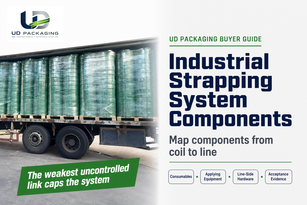
Industrial strapping system components are the consumables that surround the load, the equipment that feeds, tensions and joins them, and the line-side hardware that presents the strap and moves the package. The system is only as dependable as the lowest-rated or least-controlled link in that chain.
A strong strap can still leave the dock with a weak joint, an under-performing tensioner or a dispenser that feeds the wrong coil orientation. That is why a useful quotation has to describe a system, not merely name a strap material and a machine model.
This guide turns the system into a 12-line register, a five-station inspection walk and a component acceptance docket. It helps buyers compare high-quality strapping solutions without treating the words “plastic strapping,” “steel strapping” or “automatic” as proof that the whole system is matched.
It does not choose a material, price an automation tier or replace testing on the actual package and distribution route. Its purpose is to close scope gaps before they become damaged loads, rework or avoidable downtime.
The practical rule
Specify the coil, closure and applying equipment as one tested combination. Then add every item needed to store, dispense, guide, control and protect that combination on your line.
What Counts as an Industrial Strapping System Component?
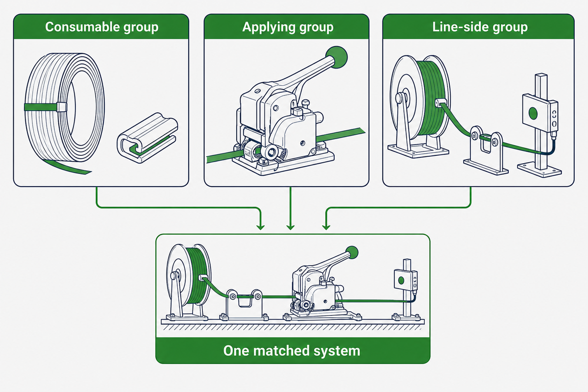
An industrial strapping system component is any item that changes how strap is stored, delivered, tensioned, joined, guided, protected or verified around a load. That definition reaches beyond the obvious strap, tensioner and sealer because a coil brake, guide track, cutter, gripper, sensor or edge protector can change the finished result.
1. Consumable group
Strap, seals, buckles and protective contact pieces that leave with the bundle or are consumed while making it.
2. Applying group
The tensioner, sealer, feed system, strapping head and internal parts that create tension and form the joint.
3. Line-side group
The dispenser, cart, chute, conveyor interface, controls and guarding that make repeated operation possible.
The current ASTM publication family supports part of this separation. ASTM D3950-23 addresses nonmetallic strapping and joining methods, ASTM D3953-15(2022) addresses flat steel strapping and seals, and ASTM D4675-14a(2022) is a selection-and-use guide. Those scopes do not amount to one performance specification for every applying and line-side component.
Machinery is not therefore unregulated. In the European Union, for example, machinery conformity obligations sit under a separate legal regime; the useful procurement distinction is between proof of regulatory conformity and proof that a particular head applies the tension and joint performance written into your specification.
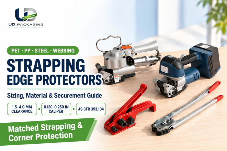
Strapping equipment can range from hand tools to fully automated cells, including portable tools for plastic strap, semi-automatic strapping machines and fully automatic strapping machines built into a production line. Choosing the right strapping arrangement and selecting the right strapping components are therefore the same task viewed at two levels: the buyer must match every function before comparing machine classes.
The 12-Line Strapping System Register
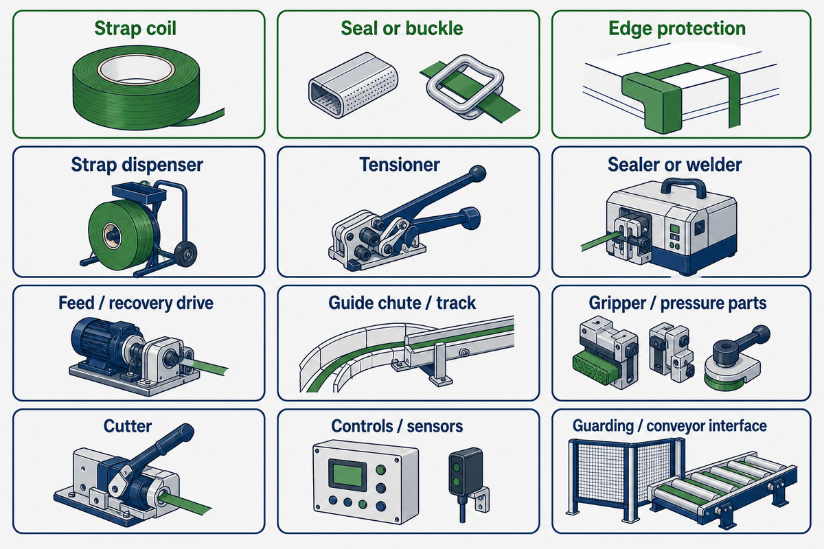
Use this register before comparing prices. ASTM D4675-14a(2022) covers the selection and use of flat strapping materials; the additional component lines here are a procurement control, not a claim that the guide standardizes the entire machine. A supplier may combine several lines inside one machine, sell them separately or exclude them, but each function still needs an owner and an acceptance record.
| Component type | Group category | What it does | State on the quotation | Failure or wear signal |
|---|---|---|---|---|
| 1. Strap coil | Consumable | Carries tension around the load | Material, grade, width, thickness, surface, break force, elongation, core and coil format | Splitting, edge damage, inconsistent feed or unexpected elongation |
| 2. Seal or buckle | Consumable | Joins the strap ends together | Part, material, finish, size, geometry, threading or crimp method and matched strap | Pull-through, rotation, open crimp, tearing or corrosion |
| 3. Edge protection | Consumable | Separates strap from cutting or crush points | Material, footprint, corner radius, crush resistance and placement | Cut strap, crushed corner or a protector that walks out of position |
| 4. Strap dispenser | Line-side | Supports the coil and controls payout | Core range, coil width and mass, orientation, brake or drag range | Overrun, loops on the floor, snatch feeding or twisted strap |
| 5. Tensioner | Applying | Pulls strap to a controlled setting | Strap range, setting range, verification method, power source and repeatability evidence | Low or drifting tension, surface damage or repeated slip |
| 6. Sealer or welder | Applying | Forms the mechanical, friction or heat joint | Closure method, matched parts, setting window and completed-joint result | Weak weld, incomplete crimp, burn-through or unstable cycle |
| 7. Feed and recovery drive | Applying | Feeds strap around the load and takes slack back | Feed direction, speed, recovery logic and compatible strap range | Short feed, reverse feed, failed retraction or repeated rethreading |
| 8. Guide chute or track | Line-side | Routes strap around the bundle | Opening, package envelope, access, alignment tolerance and release method | Snags, offset strap placement or strap escaping the track |
| 9. Gripper and pressure parts | Applying | Hold strap during tension, jointing and cutting | Part numbers, wear criteria, access and recommended spares | Slip marks, changing overlap or inconsistent joint position |
| 10. Cutter | Applying | Separates the completed cycle from the coil | Blade part, service access, expected cut condition and replacement criterion | Frayed, angled or partially cut strap ends |
| 11. Controls and sensors | Line-side | Sequence the cycle and detect packages, strap and faults | Interfaces, recipes, alarms, reset logic, records and responsibility boundary | False triggers, missed packages or faults that recur without a physical defect |
| 12. Guarding and conveyor interface | Line-side | Controls access and presents the load consistently | Package datum, height range, interlocks, guarding boundary and line ownership | Misplaced straps, unsafe access or upstream/downstream timing losses |
The two easiest omissions to miss are the dispenser and the interface that positions the load. Neither makes the joint, yet both decide whether the same strap arrives at the head with the same orientation and whether every strap lands on the intended part of the package.
Automatic machines may integrate some of these functions, while manual strapping systems and semi-automatic and fully automatic lines package them differently. Mark “included,” “separately supplied,” “by buyer” or “not applicable” beside all 12 lines instead of assuming the machine name settles the scope.
The Consumable Group: Strap Coil, Seals and Buckles
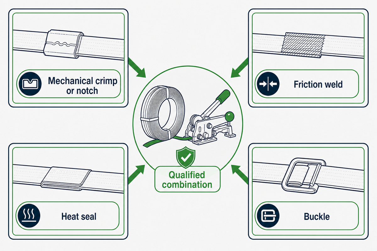
A complete coil line identifies more than polyester or polypropylene. That detail turns the register’s consumable line into a purchasable specification. Record the grade, nominal width and thickness, tolerances, surface, color if operationally relevant, break force, elongation, core dimensions, winding direction, coil mass or length, splice policy, lot identity and storage limits.
Core and coil format matter because the same strapping material can be wound for a different dispenser. A mismatch may fit on the spindle but still feed from the wrong height, direction or brake range, which turns a correct material specification into an unstable strapping process.
Write polypropylene strapping, polyester strapping, woven strapping or cord strapping rather than the loose word “poly.” Those strapping options are different plastic strapping materials or constructions, and a strapping coil for corrugate or paper products may not be suitable for heavy-duty transport and storage even when the width appears identical.
The same discipline applies across a broad range of applications, from packaging and shipping light cartons to horizontal and vertical banding of dense bundles. Material strength and flexibility matter, but the closure and applying equipment still decide whether the stated property reaches the load.
| Closure family | What the line must identify | Useful incoming check |
|---|---|---|
| Open seal | Width, length, material, finish, notch or crimp geometry and matched tool | Part identity, dimensions and installed profile on the intended strap |
| Closed seal | Inside dimensions, overlap or threading method, finish and matched strap | Free movement before tension and complete closure afterward |
| Snap-on or push-type seal | Application direction, retention feature, size and sealer geometry | Correct seating without deformation or partial engagement |
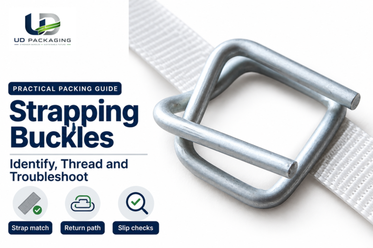
| Wire or molded buckle | Material, wire or body geometry, size, threading diagram and system rating | Threading direction, tail length, rotation and pull-through behavior |
The safest buying path is to treat the strap, closure and tool as a qualified combination. UD Packaging supplies PET strapping and supporting consumables and equipment; its product-quality and testing statements should still be checked against the report number, scope, date, sampled lot and exact product being offered rather than treated as a blanket certificate.
For dimensions and closure formats, review UD Packaging’s closure hardware for strapping systems, including its seal geometry families and strapping buckle options. If the open decision is polyester versus polypropylene, steel or another family, use the separate strap material comparison rather than expanding the component register into another materials guide.
The Applying Group: Tensioner, Sealer and the Joint They Produce

The tensioner sets how much force is applied before closure; the sealer decides how much of the strap’s potential survives at the joint. With the coil and closure family identified, the applying group turns those consumables into a joint. Manual, pneumatic and battery tools can all be appropriate, but the tool class alone does not tell you its operating setting, condition or completed-joint result.
| Closure method | How it joins | Variables to freeze | Evidence to request |
|---|---|---|---|
| Mechanical crimp or notch | A metal seal is deformed around overlapping strap | Seal part, orientation, tool and jaw profile, number and position of crimps | Completed-joint strength and failure mode for the named combination |
| Friction weld | Friction welding uses vibration to create heat between overlapping plastic strap surfaces | Weld setting, pressure, overlap, hold time, strap surface and tool condition | Joint test with settings and visible weld assessment |
| Heat seal | A heated element forms the bond before pressure and cooling | Temperature or energy control, pressure, overlap, timing and heater condition | Controlled cycle record and completed-joint result |
| Buckle | The threading path and friction lock the strap under load | Buckle identity, threading, tail, strap construction and applied tension | System-level pull result and observed rotation or slip |
A worked usable-joint calculation
Suppose a supplier identifies a strap’s break force as 5,000 N and provides a completed-joint efficiency of 72% for the exact strap, tool and setting under review. The arithmetic is 5,000 N × 0.72 = 3,600 N at the joint.
5,000 N stated strap break force × 72% stated joint efficiency = 3,600 N stated joint result
Illustrative arithmetic only—not UD Packaging test data, a safe working load or an acceptance threshold.
A quick sensitivity check makes the gap visible: within that same hypothetical, each 1 percentage-point change equals 50 N, so 70% would produce 3,500 N, 71% would produce 3,550 N and 72% would produce 3,600 N. Preserve the underlying forces and conditions instead of copying only the percentage into the purchase record.
The calculation exposes the evidence you need, but it does not rate the package. You still need to confirm how the two input figures were produced, whether the result is a minimum or a typical value, what failure occurred, and whether the intended distribution test accepts the complete unit load.
For the test boundary and failure interpretation, see how to test a strap joint. For operating choices among hand, pneumatic and battery equipment, use the separate tensioner operation guide.
Why is my strapping machine not tightening?
Start with the machine’s fault and recovery logic, then check the selected recipe, strap dimensions, coil payout, feed path, load position and tension setting. Only after those checks should you move to worn feed wheels, grippers, pressure rollers or drive parts, because a recurring low-tension symptom can come from software, setup, the consumable or mechanical wear.
Record actual tension or completed-joint evidence before and after the correction. Turning the setting upward without finding the cause may mark the product, overload the closure process or hide a dispenser and feed problem.
The Strapping Machine Group: What Sits Inside the Head
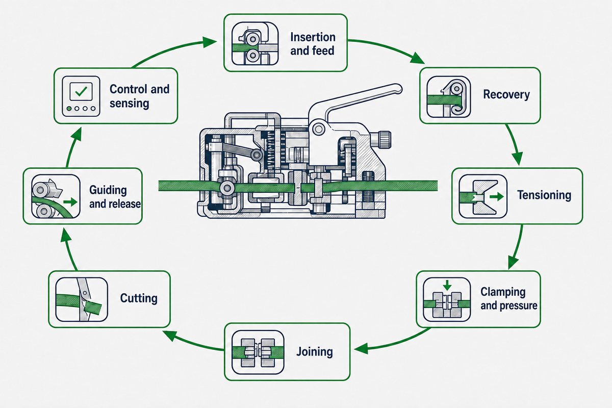
An automatic strapping machine typically has functions for insertion, recovery, final tension, clamping, joining and cutting. That sequence brings the separate tensioning and sealing functions into one machine head. Depending on the design, those functions may use separate wheels and pressure rollers or be combined around a compact strapping head.
- Insertion and feed: pushes strap through the guide track and around the package.
- Recovery: pulls back the free slack after the strap completes the path.
- Tensioning: applies the final controlled movement or force before closure.
- Clamping and pressure: holds both strap layers in position through joint formation.
- Joining: crimps a seal, creates a friction weld or applies heat and pressure.
- Cutting: releases the finished loop while preserving a feed-ready strap end.
- Guiding and release: presents the strap, then opens the track so the loop can tighten on the load.
- Control and sensing: handles package detection, cycle timing, alarms, refeed and line communication.
Two official patent records—not UD Packaging technology—show why “tension setting” is not a universal mechanism. EP 1 095 858 B1, which records Illinois Tool Works Inc. as proprietor at grant, documents a hand tool that identifies its predetermined tension through motor stall. EP 1 232 093 B1, which records Officina Meccanica Sestese S.p.A. as proprietor at grant, documents a machine tensioner in which a 0-to-n-tenths-of-a-second delay changes the effective part of a fixed 120° wheel movement, equal in that embodiment to 100 mm of strap travel.
The second document describes a high-performance context of 40 to 50 strapping cycles per minute and explains how wear can lead to incorrect adjustment. Those figures belong to that patented embodiment; they are not a throughput or service-life promise for current automatic machines.
“is subject to incorrect adjustment as a result of wear during use”
These historical grant documents describe two design embodiments, not how all current machines work or who owns any rights today. They show that the setting name alone is inadequate: the supplier should state the mechanism, adjustment method, verification procedure and acceptable result for the offered equipment.
Scope hand-off: automation tiers, utilities, installation, price bands and the model-specific safety perimeter belong in the strapping machine guide. This section only identifies the components whose condition can change feed, tension, jointing and cut quality.
Line-Side Components to Check on the Quote: Strap Dispenser, Cart and Chute
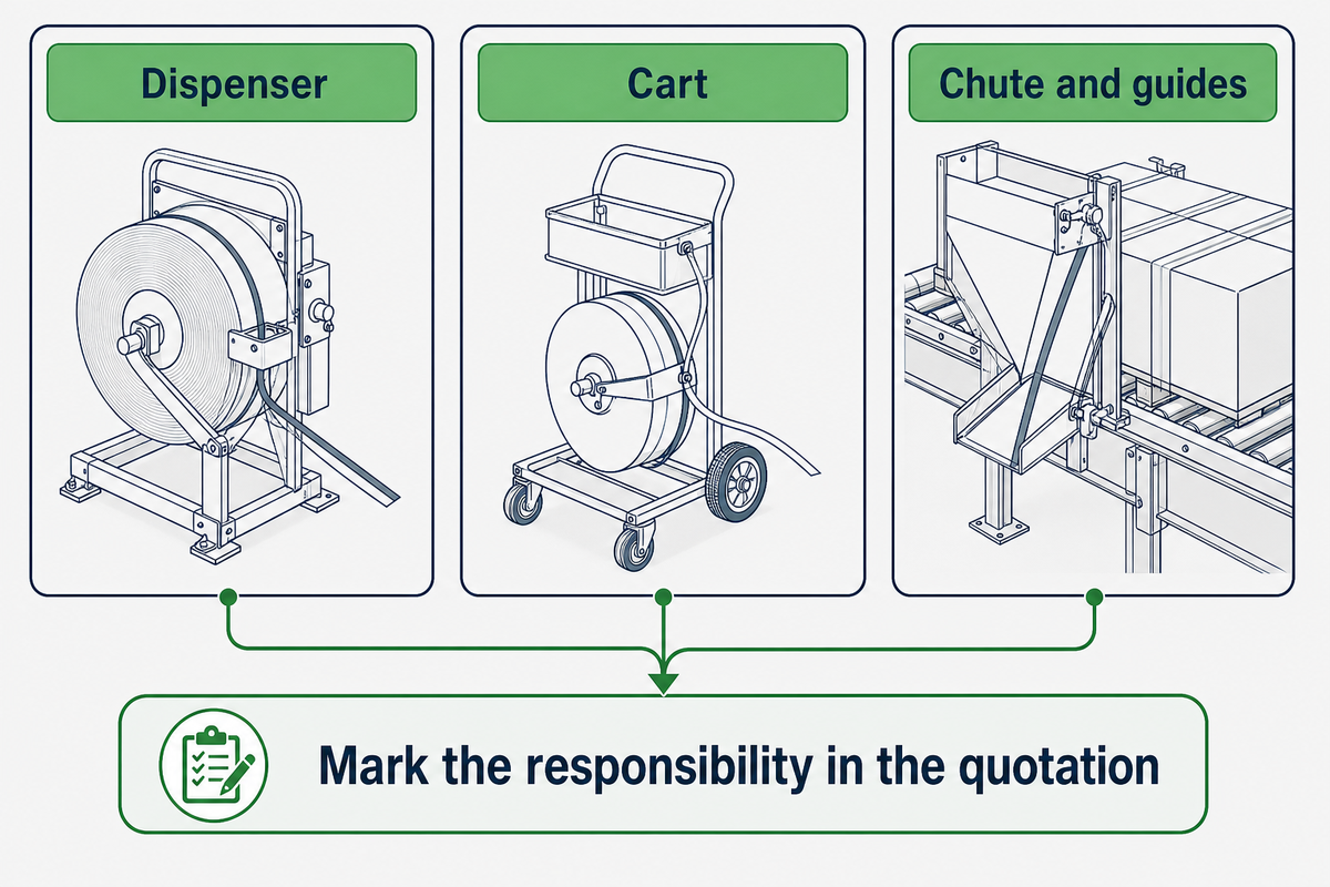
Line-side hardware is not automatically included or automatically excluded. This scope check carries the machine-head boundary outward to the dispenser, cart and guides. One machine may integrate strap feed and dispenser-side control, while another quotation may list the cart, tensioner and sealer separately.
The only safe instruction is to mark the responsibility in the quotation in front of you; ASTM D4675’s public scope is limited to flat strapping materials and does not resolve that commercial boundary. That avoids paying for an advanced head while leaving the coil on a cart whose spindle, brake and orientation were never matched to it.
Dispenser
Confirm spindle/core fit, maximum coil dimensions and mass, payout direction, brake or drag adjustment, overrun control and sensor provisions.
Cart
Confirm wheel rating, floor condition, coil retention, tool tray, seal storage, handle position and the safe method for loading a full coil.
Chute and guides
Confirm the package envelope, strap path, release action, access points, alignment checks and the procedure for clearing a severe jam.
A cart or dispenser often influences operational efficiency more than its price suggests because it controls coil handling and payout at every cycle. For manual and portable strapping tools, include the full coil-to-tool route in the trial rather than demonstrating the tool from a hand-fed strip.
Strapping carts belong on the responsibility matrix even when the strapper is portable, while inline steel strapping equipment may place dispensing hardware behind the production cell. Naming the boundary helps improve efficiency because operators know who owns coil loading, payout adjustment and access instead of discovering the gap during commissioning.
The 5-Station Weakest-Link Walk: Which Component Caps the Whole System?
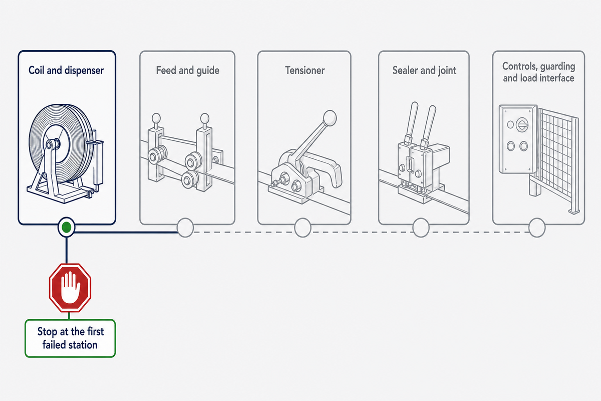
Walk the system in process order and stop at the first station whose limit, condition or evidence is below the requirement. This walk extends the responsibility matrix from line-side hardware through the joint and controls. A higher setting farther downstream cannot restore capacity already lost to damaged strap, unstable feed or an unidentified joint.
- Coil and dispenser: verify material identity, dimensions, core fit, payout direction and brake behavior. This station caps the system when the wrong strap is loaded or feed damage changes the material before tensioning.
- Feed and guide: verify the strap completes the path without twist, edge damage, snagging or inconsistent placement. This station caps repeatability when the head receives a different presentation each cycle.
- Tensioner: verify the mechanism, selected setting and actual output under the offered configuration. This station caps the system when the tool cannot reach or repeat the intended tension.
- Sealer and joint: verify the exact closure combination and completed-joint result. This station caps usable strap strength when the joint transmits less than the parent strap.
- Controls, guarding and load interface: verify package detection, datum, recipe, alarm response, interlocks and release. This station caps safe production when the process cannot repeat or faults cannot be cleared under the approved procedure.
A useful legal example reinforces the engineering logic, but its scope must stay visible. For United States commercial road-transport tiedowns, 49 CFR 393.108(a) defines the working load limit by the lowest limit of any component, explicitly including the tensioner, or the anchor points, whichever is less.
The same section’s steel-strapping table also shows why a larger dimension is not automatically a larger regulatory rating. In that table, 31.7 × 0.74 mm, 31.7 × 0.79 mm and 31.7 × 0.89 mm are each listed at 540 kg, while 31.7 × 1.12 mm and 31.7 × 1.27 mm are each listed at 770 kg.
| Width × thickness | Listed working load limit |
|---|---|
| 31.7 × 0.74 mm | 540 kg |
| 31.7 × 0.79 mm | 540 kg |
| 31.7 × 0.89 mm | 540 kg |
| 31.7 × 1.12 mm | 770 kg |
| 31.7 × 1.27 mm | 770 kg |
| 31.7 × 1.50 mm | 870 kg |
| 50.8 × 1.12 mm | 1,200 kg |
| 50.8 × 1.27 mm | 1,200 kg |
That rule does not create a global package-strapping formula, and unitizing a pallet does not automatically secure it to a vehicle. It does make one procurement lesson unusually clear: a rated strap does not make every associated component disappear from the capacity chain.
| If the first failed station is… | Do this next | Do not do this yet |
|---|---|---|
| Coil/dispenser | Correct material, format, orientation and payout control | Raise tension to overpower poor feed |
| Feed/guide | Restore alignment, clearance and clean presentation | Replace a sealer because the strap arrived damaged |
| Tensioner | Verify setting mechanism and output on the named tool | Use strap break force as proof of applied tension |
| Joint | Test the exact strap/closure/tool combination | Transfer efficiency from another closure |
| Control/interface | Resolve recipe, sensor, recovery and responsibility boundaries | Treat every recurring alarm as mechanical wear |
Wear Parts and the Symptom Each One Produces
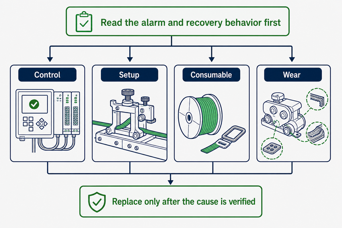
Diagnose in three branches: first ask whether the machine’s own recovery logic is intended to clear the fault; second check the settings, strap and load; third inspect wear parts. Starting with replacement parts wastes time and can briefly mask the real condition.
No credible public source in this research established one universal replacement interval across strapping machine models and environments. Use the manufacturer’s model-specific maintenance plan plus observed condition, measurement drift and finished-joint evidence.
| Symptom on the line | Suspect component or branch | Check to run | Replace when |
|---|---|---|---|
| Strap will not complete the chute | Recovery logic, feed wheel, guide or deformed strap | Read fault history; hand-check the path and inspect the leading end | A named part fails its model-specific condition check after setup and path are confirmed |
| Repeated low tension | Recipe, dispenser drag, feed wheel or gripper | Verify the selected setting and measure output before opening the head | Output stays out of the agreed range and inspection confirms wear |
| Scuffed or shaved strap | Guide edge, pressure roller, gripper or misalignment | Trace the mark upstream and compare both strap faces | A surface is damaged beyond the maker’s limit and alignment is correct |
| Weak or incomplete friction weld | Setting, contamination, pressure part or friction element | Inspect weld area, clean the path and verify the controlled setting | Joint evidence remains unacceptable and the wear criterion is met |
| Seal opens or slips | Wrong seal, jaw profile, sealer wear or orientation | Confirm part identity and inspect the finished crimp or notch | Tool geometry is out of the maker’s limit or cannot form the approved profile |
| Frayed cut end | Blade, timing, strap still under tension or poor support | Check the cut after tension release and inspect blade/support condition | The blade is chipped, dull or cannot meet the accepted cut sample |
| Changing overlap length | Feed/recovery setting, gripper slip or sensor timing | Measure overlap across consecutive cycles and correlate alarms | A holding part fails inspection after timing and setup are verified |
| Coil overruns or snatches | Dispenser brake, bearing, core fit or payout direction | Observe start/stop payout with the production coil | Brake or bearing cannot hold the stated adjustment under the coil load |
| Machine repeatedly stops with no visible damage | Sensor, control sequence, package position or designed recovery fault | Read alarm and input states before disturbing mechanical parts | Only after the control and setup branches are cleared and a component test fails |
Cold, humid or dusty warehouses can change friction, condensation, corrosion and debris loading, so a calendar copied from a clean, conditioned line may be misleading. Stock critical feed, grip, pressure, joining and cutting parts by the exact machine configuration, but connect replenishment to inspected condition and consumption history.
What are common problems with banding machines?
Common symptoms include failure to feed or rethread, low or drifting tension, strap damage, weak welds, incomplete seal crimps, frayed cuts, changing overlap, coil overrun and false stops. The same symptom can have a control, setup, consumable or wear cause, so read the machine’s alarm and recovery behavior first, then verify the strap and settings before replacing parts.
Acceptance Evidence to Demand for Each Component at RFQ
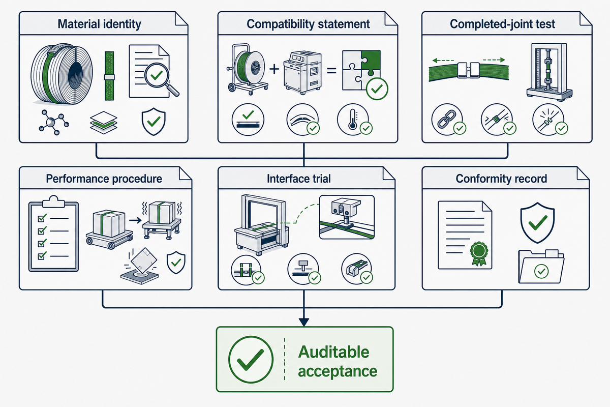
A request for quotation should make each claim auditable. “Suitable for PET” is not enough when the delivered strap, closure, tool and setting can each change the finished joint. The current ASTM D3950 publication scope separately names nonmetallic strapping and joining methods, which is why material evidence and completed-joint evidence belong in distinct rows.
| Component | Document to demand | What it must state | How to verify |
|---|---|---|---|
| Strap coil | Controlled specification and lot record | Material, grade, dimensions, tolerances, test properties, core and lot identity | Match labels and measured incoming sample to the offered document |
| Seal or buckle | Part drawing and compatibility statement | Geometry, material, finish, strap range, tool and installation direction | Inspect the delivered part and one completed joint |
| Strap/closure system | Completed-joint test report | Exact combination, conditioning, settings, results and failure locations | Recalculate reported efficiency and repeat the agreed acceptance test |
| Dispenser/cart | General arrangement and rating sheet | Core range, coil envelope/mass, orientation, brake, wheels and retention | Load the production coil and observe controlled payout |
| Tensioner | Performance and verification procedure | Strap range, setting mechanism, output range, tolerance and check method | Witness checks at low, working and high agreed settings |
| Sealer/head | Process window and wear-part list | Closure method, controlled parameters, part numbers and reject indicators | Review consecutive joints and destructive-test samples |
| Guide/chute | Layout and package-envelope drawing | Path, clearances, datum, access, release and jam-clear method | Run minimum and maximum agreed package conditions |
| Controls/interfaces | Functional description and interface list | Sequence, recipes, signals, alarms, recovery and data ownership | Execute normal, boundary and fault scenarios in the acceptance plan |
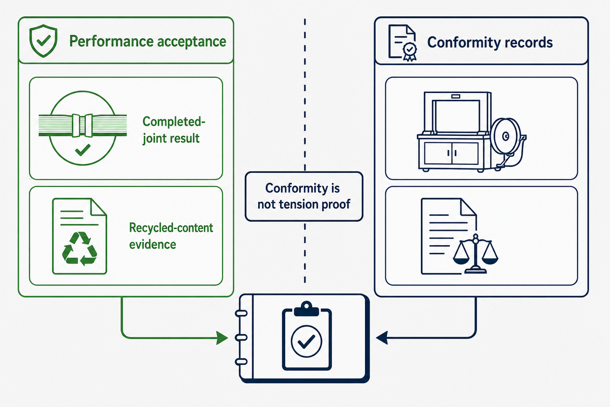
| Guarding/machinery | Applicable conformity and technical documentation | Jurisdiction, machine identity, scope, declaration and residual-risk information | Confirm the offered machine and market, without treating conformity as tension proof |
Copy these rows into the RFQ
| RFQ row | Required input | Supplier response | Acceptance evidence |
|---|---|---|---|
| Load and route | Package geometry, mass, surfaces, settling, handling and distribution conditions | Design basis and exclusions | Agreed package/distribution trial |
| Consumable set | Strap, closure and protector identities | Controlled part list | Incoming and joint records |
| Applying set | Tension and seal method, tool/head and settings | Operating window and limits | Output and completed-joint tests |
| Line-side set | Dispenser, cart, chute, conveyor and controls | Included/excluded responsibility matrix | Loaded-coil and package-range trials |
| Spares/service | Named wear parts, criteria, access and support boundary | Part list and maintenance plan | Inspection and service demonstration |
UD Packaging states that its products undergo quality control and SGS product-quality testing, and that its plastic tensile and joint-strength practices reference GB/T 1040.1-2018 and GB/T 1040.3-2006. Ask for the current report, test object, method scope, lot relationship and measured result; do not turn a company-wide statement into a value for an unidentified roll.
Also check whether the named edition is the one required on the buying date. The official record for GB/T 1040.1-2018 identifies that edition; buyer and supplier should verify the edition required by the contract and applicable standard registry before making it an acceptance criterion.
Bring a system brief, not a strap name
Send the 12-line register, package and route details, intended consumables, required joint evidence and open responsibility rows. UD Packaging can review the PET strapping, closure and equipment boundary against that brief without inventing missing acceptance values.
What Is Changing in How Components Get Specified?
For procurement, state the closure method, its controlled settings and the completed-joint result together. “The machine welds PET” describes a capability; it does not say what percentage or force the identified joint achieved, under which conditions, or how production will keep it inside the accepted window.
That documentation applies whether PET is being considered as an alternative to steel or whether a plant is comparing plastic strapping tools with a fixed head. The open question is not which catalogue offers more strapping applications; it is whether each component can be tied to a controlled input and a reviewable result.
Search-demand data from this run show a stable rather than exploding topic. Fourteen of 20 tracked component terms stayed flat or inside a stable band over the measured 12 months, and no term showed sustained erosion; that is search behavior, not market size or shipment data.
Why there is no market-size figure here: public publishers put apparently comparable strapping markets in irreconcilable ranges. Repeating one estimate or growth rate would add false precision to a component specification, so the article uses primary standards, regulations, patents and measured keyword demand instead.
Recycled-content evidence is becoming another coil-level document, but the responsible actor and required declaration depend on the jurisdiction and transaction. In the European Union, the Packaging and Packaging Waste Regulation entered into force on 11 February 2025 and applies from 12 August 2026; a February 2026 delegated act exempts pallet wrapping and straps from the 100% reuse requirement while keeping them inside the wider 40% reusable transport-and-sales-packaging target from 1 January 2030.
The exemption page is specific to European Union law and does not identify a particular buyer’s statutory role. Confirm who designs, brands, imports or places the packaging on the relevant market before assigning the document to a supplier or customer.
Machinery documentation also has a dated transition. The European Commission machinery page states that machinery placed on the European Union market before 20 January 2027 must comply with Machinery Directive 2006/42/EC, while Regulation (EU) 2023/1230 applies mandatorily from that date.
Keep performance acceptance and conformity records in the same docket but in separate rows. A declaration or CE marking addresses a legal conformity route; it does not by itself prove the repeatability of applied tension, joint efficiency or package performance.
Frequently Asked Questions
What are the main components of an industrial strapping system?
The main components are the strap and closure, the equipment that feeds, tensions, seals and cuts it, and the line-side hardware that stores the coil, guides the strap, positions the load and controls the cycle. A complete review also includes edge protection, sensors, guarding, conveyor interfaces and the acceptance documents for the exact combination.
What are common problems with banding machines?
Frequent problems include feed or rethread failure, low tension, damaged strap, weak welds, incomplete crimps, frayed cuts, coil overrun and false stops. Read the alarm and recovery state first, then check recipe, consumable, payout and load position before moving to feed wheels, grippers, pressure parts, heaters, friction elements or cutters.
How do you tighten a strapping machine?
Use the machine maker’s model-specific adjustment and verification procedure, because different designs can translate a setting into tension in different ways. Confirm the correct recipe and strap, measure the resulting output, inspect the package and joint, and never raise a setting simply to overcome poor coil payout or a damaged feed path.
What are the different types of strapping?
Common industrial families include polypropylene, polyester or PET, flat steel, composite cord and woven polyester. Each has different elongation, recovery, edge, temperature and closure behavior; use the dedicated material guide when material selection, rather than system completeness, is the open decision.
Which strapping component should be specified first?
Start with the load: geometry, mass, contact surfaces, sharp edges, temperature, settling behavior, handling method and distribution route. Add customer, carrier and jurisdiction-specific constraints before selecting a coil, because those facts decide what the finished unit must withstand.
Next define the strap-and-closure result, including how completed-joint performance and package acceptance will be measured. Select applying equipment only after that result is visible, then specify the dispenser, guide, controls, guarding, conveyor datum and recovery behavior needed to repeat it.
This order prevents a common reversal: buying a machine first and later forcing an available coil and seal to fit it. It also leaves a clear evidence path when one component changes, because the team can revalidate the affected station instead of silently assuming that every other result still applies.
How much does a banding machine cost?
Price depends on automation, package range, head, utilities, conveyor, controls, guarding and installation. Use the machine buying guide for a scoped comparison.
References & Sources
- ASTM D3950-23 — Standard Specification for Strapping, Nonmetallic (and Joining Methods). Official publication and scope page.
- ASTM D3953-15(2022) — Standard Specification for Strapping, Flat Steel and Seals. Official publication and scope page.
- ASTM D4675-14a(2022) — Standard Guide for Selection and Use of Flat Strapping Materials. Official publication and scope page.
- Electronic Code of Federal Regulations, 49 CFR 393.108. Working load limits for tiedown assemblies within its stated United States road-transport scope.
- European Patent EP 1 095 858 B1 — Hand strapping tool. Official grant PDF; Illinois Tool Works Inc. is the grant-recorded proprietor.
- European Patent EP 1 232 093 B1 — Tensioning device for strapping machines. Official grant PDF; Officina Meccanica Sestese S.p.A. is the grant-recorded proprietor.
- European Commission — Pallet wrapping and straps exempt from 100% reuse requirement, 25 February 2026.
- European Commission — Machinery legislation. Directive and Regulation transition dates.
Evidence boundary: Numerical examples in this article are explanatory unless explicitly attributed to a source. They are not UD Packaging product results, safe working loads, legal advice or acceptance criteria for an unidentified package.