Get in touch with UD Packaging Company

Updated August 2026 · By XCX
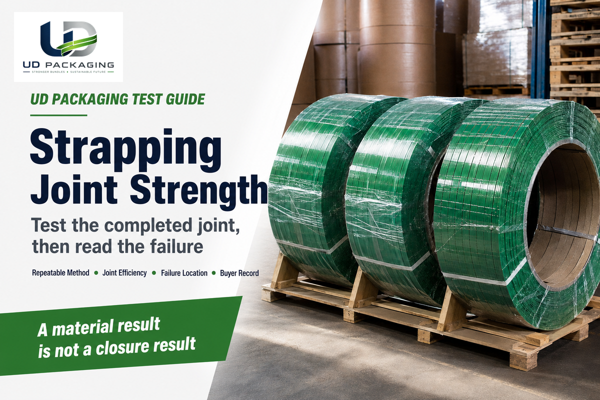
Strapping joint strength is the peak force sustained by a completed strap joint under a stated test method. It is not the break strength of an unjointed strap. Joint efficiency equals joint peak force divided by unjointed strap peak force, multiplied by 100. Record the material, joint method, tool settings, conditioning, specimen geometry, and failure location before comparing results.
A percentage alone isn’t enough to approve a closure. The numerator and denominator must come from identified specimens tested on a comparable basis, and the result needs a failure location. Without that context, a high number can hide strap slip, a grip problem, mixed conditioning, or an unmatched tool setting.
This guide explains a repeatable test, a transparent calculation, failure diagnosis, and the records a buyer should request. It doesn’t create a universal pass percentage, safe working load, sample count, or UD Packaging product result. Those decisions belong in the written test plan for the actual strap, closure, tool, package, and distribution route.
Search-scope boundary: “Joint strength food,” “joggle lap joint,” and “plug joint” refer to different food, sheet-metal, or woodworking questions. “Joint health” is a medical phrase and is also outside this guide. Here, “strap joint” means an industrial packaging closure.
Quick Specs: what a comparable result contains
- Peak force for every completed-joint specimen, with unit.
- Peak force for the unjointed comparison specimens, with the same unit.
- Joint efficiency calculation with both raw forces preserved.
- Strap identity, lot, width, thickness, surface, and preparation.
- Closure type, tool identity, settings, condition, and operator or station.
- Conditioning temperature, relative humidity, duration, and prior exposure.
- Specimen geometry, grip arrangement, pull direction, rate, and machine record.
- Failure location, photograph or observation, decision, and retest trigger.
What Strapping Joint Strength Actually Measures
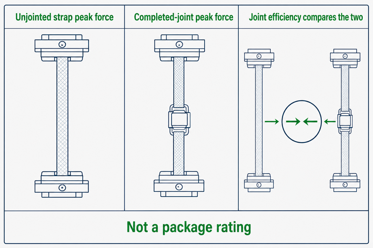
Strapping joint strength measures the force sustained by a formed closure: for example, a friction weld, metal seal, or sealless joint. Strap breaking force measures an unjointed specimen. Joint efficiency compares the two, but it doesn’t turn either value into a package rating.
The distinction matters because a closure is a process, not just a component. Even after you compare the unjointed material baseline, a high-rated strap can still produce an unstable joint when its overlap, seal geometry, weld energy, tool condition, or surface contamination changes. Conversely, a strap-body break away from a sound joint may show that the closure wasn’t the limiting location in that specimen.
| Reported value | What it proves | What it does not prove |
|---|---|---|
| Unjointed strap peak force | The specimen’s peak force under the stated material test. | Closure quality, joint efficiency, retained tension, or package performance. |
| Completed-joint peak force | The tested joint assembly’s peak force under the recorded setup. | Every tool, lot, setting, environment, or shipping route. |
| Joint efficiency | The joint result relative to its stated unjointed comparison. | A universal acceptance threshold or safe working load. |
The public scope of ASTM D3950-23 is useful for this boundary because it covers nonmetallic strapping and joining methods and treats breaking strength and joint strength as distinct properties. ISO 527-3 addresses tensile properties of plastic films and sheets; it should not be presented as proof of a completed strap joint.
How to Run a Repeatable Strapping Joint Strength Test
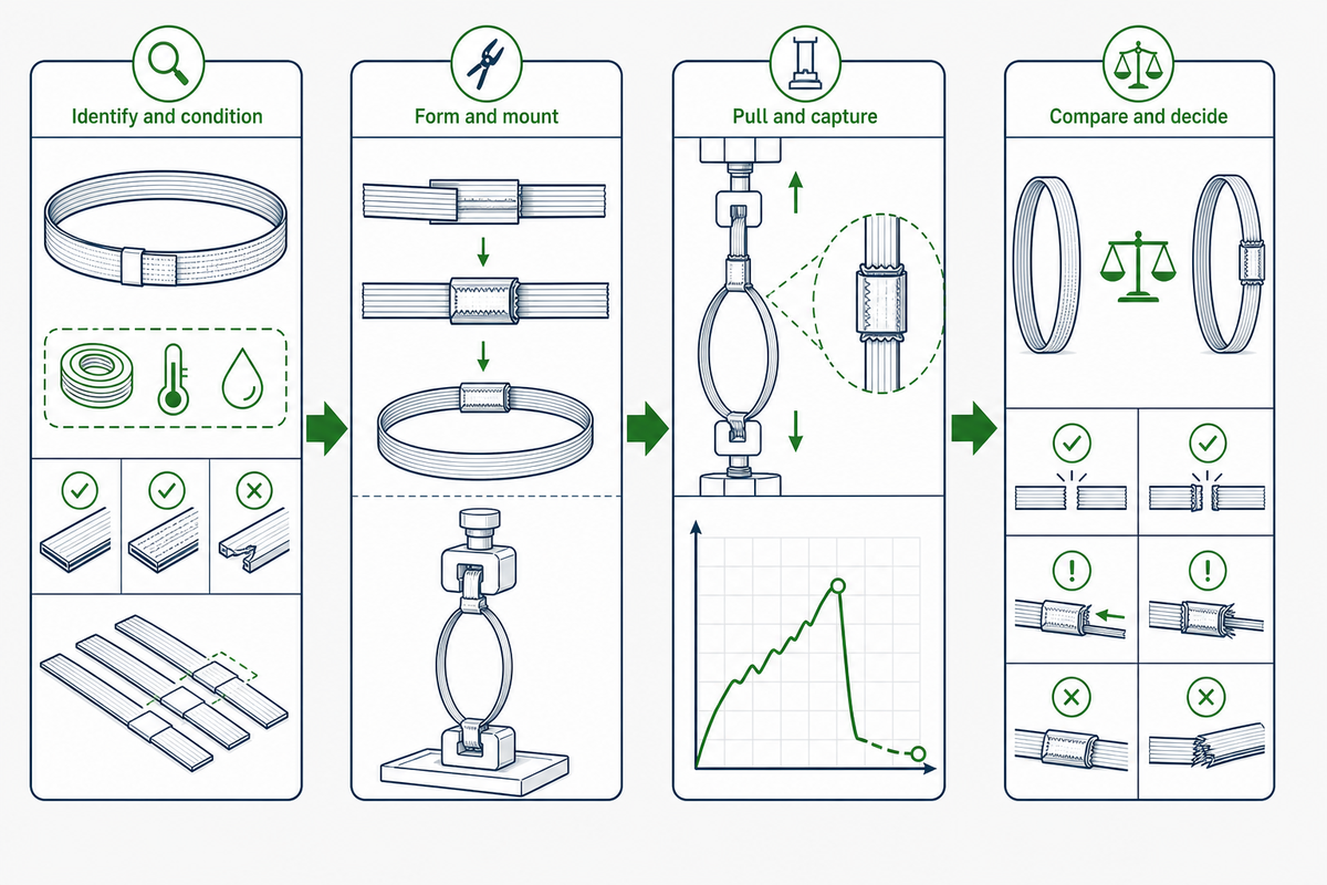
How do you test strapping joint strength?
Write the method before making specimens. The goal isn’t merely to pull a loop until something moves; it’s to create a comparison another laboratory or production team can reproduce without guessing the strap, joint, conditioning, grips, rate, or result rule. Record joint alignment and the mechanical stability of the grips instead of assuming the fixture stayed square.
- Identify the system — record strap material, lot, dimensions, surface, closure, tool, settings, maintenance state, and specimen maker.
- Condition the specimens — state temperature, relative humidity, duration, and prior exposure instead of writing only “room conditions.”
- Form the joint — use the declared overlap, seal or weld process, tool orientation, tension setting, and hold or cooling practice.
- Mount the specimen — align the load path, protect against grip damage, and record specimen geometry, grip spacing, and pull direction.
- Run the pull — use the stated force range and test rate on a machine whose force system has a current verification record appropriate to the method.
- Capture the failure — save peak force, curve or trace when available, failure location, visible slip, and a photograph before removing the specimen.
- Compare and decide — calculate each result under the written rule, show dispersion and the minimum, then apply the pre-agreed accept, investigate, or retest action.
ISO 7500-1 concerns verification and calibration of the force-measuring system of static uniaxial testing machines. That is a machine-confidence boundary, not a PET-joint test method. The method still needs the strapping-specific specimen, joint, conditioning, grips, rate, and failure record.
Conditioning deserves its own line in the record. ASTM D618 shows why temperature, relative humidity, and conditioning history matter when comparing plastic test results. “Same strap, same tool” is incomplete if one specimen set was tested after a different storage or conditioning history.
Joint Efficiency Formula and Worked Example
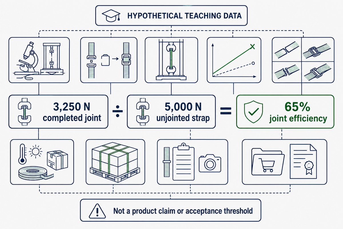
Joint efficiency (%) = completed-joint peak force ÷ unjointed strap peak force × 100
Keep both forces, their units, specimen identities, and comparison conditions beside the percentage.
For a hypothetical example, divide a 3,250 N completed-joint result by a 5,000 N unjointed result. Multiplying 0.65 by 100 gives 65% joint efficiency. These numbers are teaching data only. They aren’t UD Packaging test data, a product claim, or an acceptance threshold.
Hypothetical condition record: 16.0 mm × 1.00 mm PET strap; 23 °C and 50% relative humidity for 24 hr; 30 min from conditioning to test; 300 mm free length; 200 mm/min pull rate; 100 mm overlap; 10 s hold. The four teaching efficiencies are 62.0%, 65.0%, 68.0%, and 71.0%. These values demonstrate record structure only and do not recommend a specimen size, conditioning schedule, speed, or pass level.
| Specimen | Joint peak force | Unjointed comparison | Efficiency | Observed failure |
|---|---|---|---|---|
| J-01 | 3,250 N | 5,000 N | 65.0% | Joint separation |
| J-02 | 3,400 N | 5,000 N | 68.0% | Strap slip at joint |
| J-03 | 3,100 N | 5,000 N | 62.0% | Joint separation |
| J-04 | 3,550 N | 5,000 N | 71.0% | Strap-body break |
Don’t report only the 66.5% mean. In this teaching set, the minimum is 62.0%, the maximum is 71.0%, and the failure mode changes. That variation is precisely why every specimen belongs in the record. NIST Technical Note 1297 supports explaining what was measured and how uncertainty components were evaluated; it doesn’t prescribe one universal strap sample count.
Read the Failure Location Before Accepting the Number
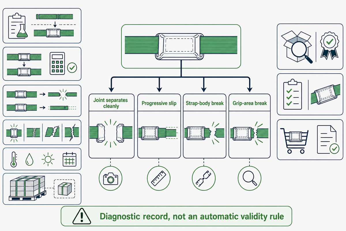
A peak-force value without failure location is incomplete evidence. The force tells you when the recorded maximum occurred; the failed surface and movement pattern tell you whether the joint, strap body, or test setup governed the specimen. Use the following Break–Slip Diagnostic Grid as a diagnostic record, not as an automatic validity rule.
9-Observation Break–Slip Diagnostic Grid
| Observation | What may have governed | Record now | Next action |
|---|---|---|---|
| Joint separates cleanly | Weld bond, seal engagement, notch, overlap, or surface condition | Separated faces, overlap, settings, force | Compare the joint process with the written setup |
| Progressive slip through seal | Seal geometry, crimp, tooth engagement, strap surface | Slip distance, seal orientation, tool identity | Inspect compatibility and tool wear before retest |
| Slip within friction weld | Weld energy, pressure, cooling, contamination, alignment | Weld area, residue, settings, hold practice | Restore the controlled process window |
| Strap breaks beside joint | Stress concentration, heat-affected zone, edge damage | Distance from joint, edge appearance, photograph | Review preparation and joint geometry |
| Strap breaks in free span | Strap body may govern that specimen | Break location, dimensions, lot, force | Keep the result; check method-specific validity rules |
| Grip-area break | Grip pressure, abrasion, bending, or misalignment | Grip marks, distance, mounting photograph | Investigate setup before treating it as closure evidence |
| Specimen twists during pull | Off-axis loading or unequal grip alignment | Twist direction, grip positions, video if available | Correct alignment and repeat under the plan |
| Force drops and recovers | Intermittent slip, machine response, or joint progression | Force trace, audible events, visible movement | Review the trace with the physical specimen |
| Mixed failure across set | Multiple limiting mechanisms or unstable preparation | Every mode and its specimen force | Do not average away the mode change |
Do
- Photograph both joint faces after the test.
- Mark the failure distance from the joint and grips.
- Keep the force trace with the physical observation.
- Investigate mixed modes before combining results.
Don’t
- Call every strap-body break an automatic pass.
- Discard a low result without a written reason.
- Rename grip damage as joint separation.
- Compare forces produced under unmatched conditions.
How Closure Type Changes the Failure Mode
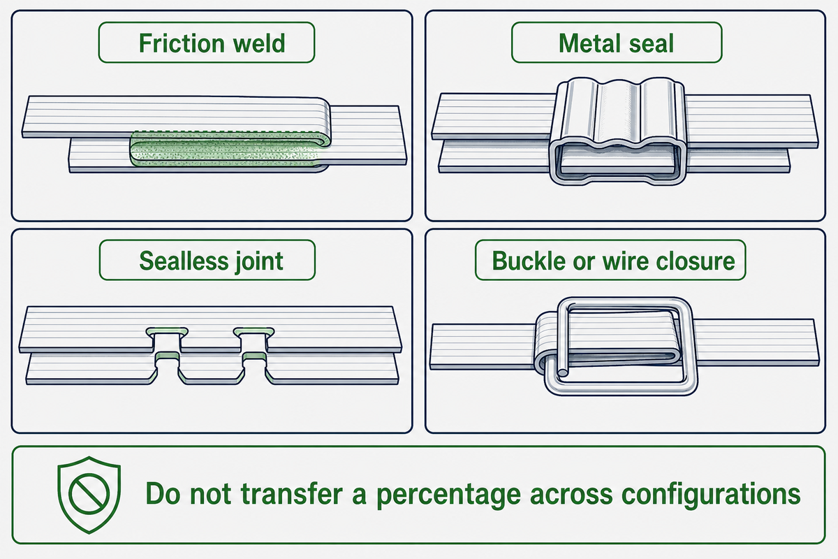
Friction-weld, metal-seal, and sealless joints don’t share one assumed efficiency. Each mechanism creates a different load path and a different group of controllable variables. A supplier percentage for one closure can’t be transferred to another seal geometry, tool, surface, or strap construction without evidence.
| Closure | Variables to freeze | Useful observations |
|---|---|---|
| Friction weld | Tool model, weld setting, pressure, overlap, hold or cooling, battery state, strap surface | Welded area, unmelted zone, burn-through, slip, debris, off-center contact |
| Metal seal | Seal part and orientation, crimp or notch geometry, tool model, wear, strap dimensions | Seal opening, notch tear, progressive slip, asymmetric engagement |
| Sealless joint | Tool model, joint pattern, die condition, strap grade and dimensions, alignment | Interlock deformation, tear path, incomplete engagement, tool marks |
| Buckle or wire closure | Buckle identity, threading path, strap type, applied tension, tail length | Rotation, creep, cutting, pull-through, local bending |
When a specification uses a specified strapping seal, bind the seal to the tested strap dimensions and tool. “Fits 16 mm” isn’t a complete joint-strength statement. Record the exact part, installed geometry, tool, and observed failure.
How strong is metal strapping?
There is no single material-wide value. Flat steel strap and its seal joint are separate evidence items. ASTM D3953-15(2022) applies to flat steel strapping and seals; it should not be cited as the governing specification or acceptance threshold for a PET joint.
Five Variables That Make Joint Tests Drift
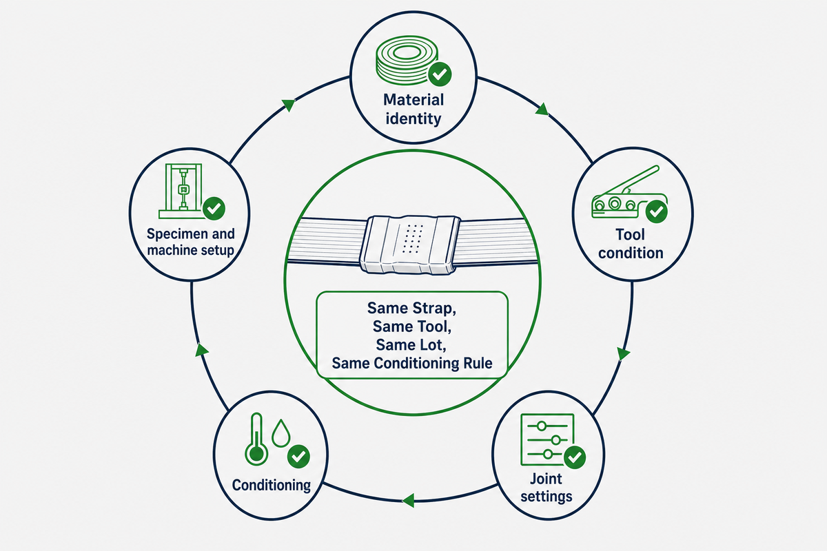
The most useful control rule is simple: Same Strap, Same Tool, Same Lot, Same Conditioning Rule. Add the same specimen preparation and test setup when comparing data. If any controlled field changes, treat the result as a different condition until the written plan says otherwise.
- Material identity: lot, resin or construction, surface, width, thickness, age, storage, and visible damage.
- Tool condition: exact model, serial or station, battery state, calibration or verification status, maintenance, wear parts, and cleanliness.
- Joint settings: applied tension, weld or seal setting, overlap, alignment, pressure, cycle, and cooling or hold practice.
- Conditioning: temperature, relative humidity, duration, prior exposure, and time between conditioning, joint formation, and testing.
- Specimen and machine setup: preparation, geometry, grips, gauge or free length, pull direction, rate, operator, and data-acquisition rule.
The tool included in the tested setup is therefore part of the tested system, not an interchangeable accessory. Production checks should identify settings and tool condition with enough detail to reproduce the laboratory or qualification condition.
From Laboratory Result to a Packaging Decision
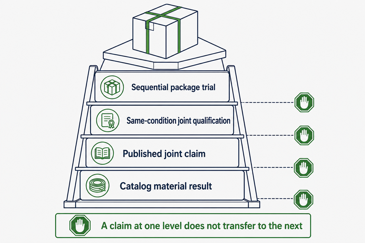
A static completed-joint test qualifies the recorded test condition. It doesn’t, by itself, prove that a strapped box or pallet will survive settling, vibration, impact, handling, heat, moisture, abrasion, or sharp-edge exposure. Keep material results, published joint claims, same-condition joint qualification, and sequential package trials as separate evidence levels; a claim at one level doesn’t transfer to the next.
- Catalog material result: screens a named strap but doesn’t prove a closure.
- Published joint claim: screens a closure idea but doesn’t prove the buyer’s tool, lot, or conditioning.
- Same-condition joint qualification: supports the tested strap–closure–tool–conditioning configuration.
- Sequential package trial: challenges the unopened shipping unit under the intended distribution hazards and pre-agreed criteria.
ASTM D4675-14a(2022) frames flat-strapping selection as a starting point and emphasizes user testing. ASTM D4169-23e1 addresses sequential performance testing of shipping containers and systems on the same unopened shipping unit; it is not a strapping-joint test method.
For the application handoff requested in this guide, review the strapping setup for the cartonized load. Use that page to discuss the box application, while keeping joint qualification and package-route validation as separate evidence steps.
The Specimen Trace Sheet: Acceptance and Retest Plan
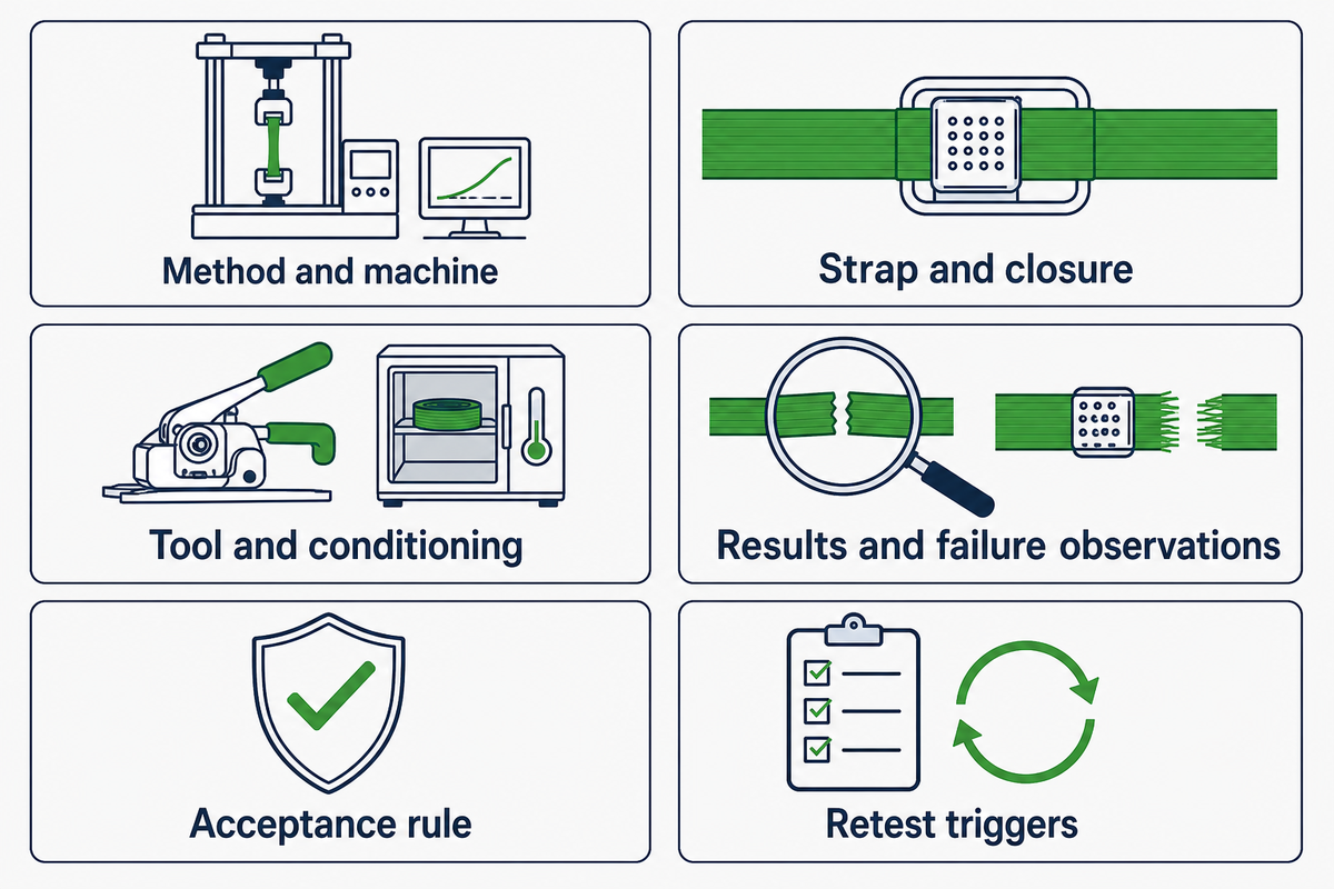
The Specimen Trace Sheet is an editorial buyer record, not a standard form. Its job is to keep the method, condition, every result, failure modes, decision, and change triggers together. Agree on the acceptance rule and specimen count before testing; don’t choose them after seeing the data.
| Record field | Minimum entry | Why it matters |
|---|---|---|
| Method and revision | Named procedure, edition, local instruction revision | Prevents silent method changes |
| Machine | Model, ID, force range, verification status and date | Connects the force result to an identified system |
| Strap | Material, product, lot, width, thickness, surface | Defines the tested material |
| Closure | Joint type, seal or buckle part, overlap and orientation | Defines the load-transfer mechanism |
| Tool and settings | Model, ID, condition, tension and weld or seal settings | Makes production reproduction possible |
| Conditioning | Temperature, relative humidity, duration, prior exposure | Separates environmental history from material variation |
| Specimen setup | Geometry, free length, grips, pull direction, rate | Controls alignment and comparison basis |
| Individual results | Every peak force and efficiency, not only the mean | Exposes low results and dispersion |
| Failure observations | Location, mode, slip, photograph, force trace | Shows what governed each result |
| Summary | Count, mean, minimum, maximum, dispersion method | Supports a transparent decision |
| Acceptance rule | Pre-agreed criteria and decision owner | Stops post-result threshold changes |
| Retest triggers | Material, lot, dimensions, tool, settings, site, method, route changes | Keeps approval inside its evidence boundary |
NIST’s repeated-measurement guidance supports preserving observations and dispersion, but it doesn’t supply one mandatory count for every strapping program. A cotton-bale specification, for example, can use its own application-specific average and minimum rules; those values can’t be transferred to boxes, pallets, bricks, metal coils, or timber.
For a deeper handoff between buyer and supplier, carry the raw specimen record into technical review. That review should complement, not replace, the raw specimen record.
What to Put in an RFQ or Incoming Inspection Record
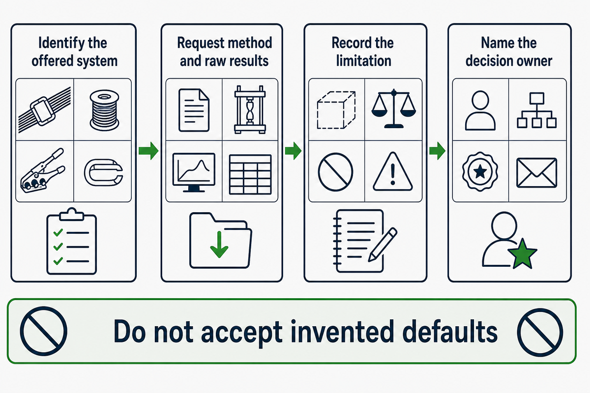
A request for quotation should bind the offered strap, closure, and tool condition to evidence that can be repeated. The current research didn’t establish defensible universal ranges for these fields, so the buyer should supply application requirements or request declared values and test reports rather than accept invented defaults.
| Request field | Evidence to request | Limitation to record |
|---|---|---|
| Strap identity | Material, grade, surface, width, thickness, tolerance, lot traceability | Applies only to the named product and lot controls |
| Material test | Method, specimen, conditioning, individual results, units, report revision | Does not prove the completed joint |
| Joint result | Closure, tool, settings, raw forces, efficiency, failures | Applies only to the recorded condition |
| Seal or buckle | Part number, material, geometry, compatible strap dimensions | Nominal width alone is not compatibility proof |
| Tool compatibility | Exact model, approved range, settings, maintenance and wear controls | Visual fit is not process validation |
| Conditioning and exposure | Storage, temperature, humidity, ultraviolet, chemical and time boundaries | Request evidence relevant to the route |
| Package trial | Representative load, strap pattern, edges, dwell, hazards, acceptance criteria | A joint pull is not a whole-package trial |
| Change control | Notification rules for material, dimensions, process, site, tool or method | Approval does not automatically follow a change |
| Report ownership | Issuer, date, revision, scope, specimen link and decision owner | A logo alone does not prove scope or lot coverage |
UD Packaging can discuss PET strapping, seals or buckles, and manual through automatic equipment as a combined procurement scope. The acceptance record should still identify the offered configuration and the supporting report; this article doesn’t claim a specific roll, joint percentage, certification scope, lead time, capacity, or customer outcome.
Need to compare a strap, closure, and tool under one documented condition? Share the material, package, route, joint method, tool, and acceptance fields with UD Packaging.
Frequently Asked Questions
Is strap breaking strength the same as strapping joint strength?
Answer
No. Strap breaking strength is obtained from an unjointed material specimen under a stated method. Strapping joint strength is the peak force sustained by a completed closure under its recorded method. Joint efficiency compares the two, but neither value alone establishes a package safe working load or distribution result. Keep the raw forces, units, specimen conditions, and failure locations together before approving the comparison.
How do you test strapping joint strength?
Answer
Identify the strap, lot, closure, tool, settings, conditioning, specimen geometry, grips, pull direction, rate, and machine. Form and mount the joint consistently, pull it under the written method, then record every peak force, failure location, photograph, and force trace. Apply an acceptance rule and sample count agreed before testing. If the setup or conditioning changes, classify it as a new condition instead of merging the results.
What is strapping joint efficiency?
Answer
Strapping joint efficiency is the completed-joint peak force divided by the comparable unjointed strap peak force, multiplied by 100. Report the percentage with both raw forces, units, specimen conditions, and failure mode. A percentage without its numerator and denominator can’t show whether the comparison basis is valid. It’s a relative test result, not an automatic package rating or universal pass threshold.
What causes a PET strap joint to slip?
Answer
Possible causes include unmatched strap and tool, low weld energy or pressure, contaminated surfaces, short overlap, insufficient cooling or hold time, worn parts, off-axis loading, seal engagement, or test-grip movement. Record where slip starts before changing settings.
How many joint specimens should be tested?
Answer
There’s no one defensible count for every strap, method, production risk, and application. Set the count in the applicable method or buyer test plan before testing. Consider expected variability, consequence of failure, process changes, and the precision needed for the decision. Report every specimen, the minimum, maximum, mean, selected dispersion measure, and failure-mode distribution. Preserve excluded results with the written reason instead of deleting them from the record. If the method, customer specification, regulated package, or application standard sets a count, follow that requirement rather than a generic blog number. Increase the evidence plan when a new lot, tool, setting, site, method, conditioning history, or failure pattern could change the decision, and name the approval owner before testing starts.
How strong is metal strapping?
Answer
Metal strapping has no single strength. The value depends on material, grade, width, thickness, finish, specimen, and test method. The seal or sealless joint also has its own result. Compare the exact steel strap and joint under the applicable specification, record the failure location, and keep package validation separate; don’t transfer its number or acceptance rule to PET.
Method and Evidence Note
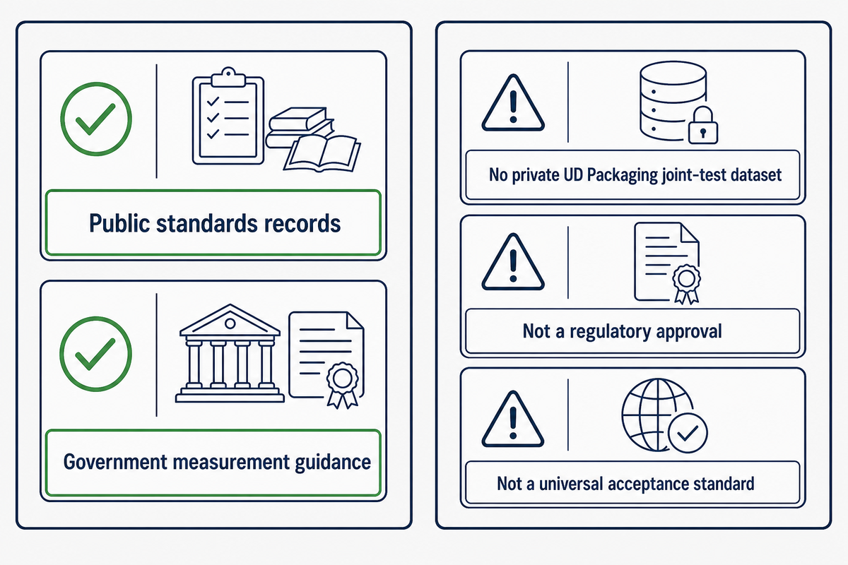
This guide was built from public standards records, government measurement guidance, current related-question evidence, and a review of packaging-industry language. Firecrawl and Ahrefs were unavailable during this run, so those coverage routes were disclosed and replaced with the approved web-search fallback. Exact keyword volume wasn’t available, and no private UD Packaging joint-test dataset was supplied.
The Break–Slip Diagnostic Grid, Specimen Trace Sheet, and Same Strap, Same Tool, Same Lot, Same Conditioning Rule are editorial decision aids. They are not ASTM or ISO forms, regulatory approvals, customer case studies, or universal acceptance standards.
References & Sources
- ASTM D3950-23, Standard Specification for Strapping, Nonmetallic (and Joining Methods) · ASTM International
- ASTM D3953-15(2022), Standard Specification for Strapping, Flat Steel and Seals · ASTM International
- ASTM D4675-14a(2022), Standard Guide for Selection and Use of Flat Strapping Materials · ASTM International
- ASTM D618-21, Standard Practice for Conditioning Plastics for Testing · ASTM International
- ASTM D4169-23e1, Standard Practice for Performance Testing of Shipping Containers and Systems · ASTM International
- ISO 527-3:2018, Plastics, Determination of tensile properties, Part 3 · International Organization for Standardization
- ISO 7500-1:2018, Verification and calibration of force-measuring systems · International Organization for Standardization
- NIST Technical Note 1297, Guidelines for Evaluating and Expressing Measurement Uncertainty · National Institute of Standards and Technology
- NIST/SEMATECH Engineering Statistics Handbook, data collection for repeatability · National Institute of Standards and Technology
- Specifications for Bale Ties · Joint Cotton Industry Bale Packaging Committee